 Input
Devices
Input
Devices
This
week our assignment was to design and build a circuit board that has a sensor
on it and read it. We used our FabISPs we built
earlier in the course. I chose to use a 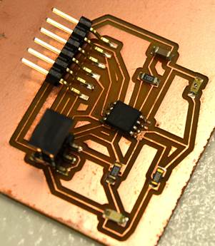 phototransistor
as my sensor. On my final project, I will use an indicator light (a blue led)
to tell me if my solar panels are receiving enough power to charge my phone. This
way, I won’t have to reach into my bag to make sure I was in a sunny enough
spot to charge. Eagle Cad was trickier
this time. I had to find the correct settings to route my board without holes.
Even then, when my instructor reviewed my first board, she said I should start
all over. This time taking care to place my traces with more clearance the
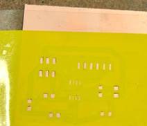
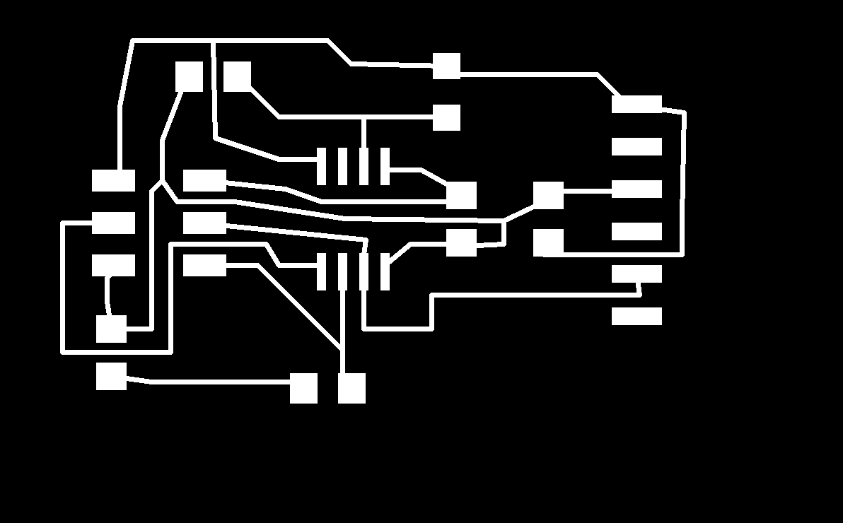
components. Just like last time, I milled my board out on our Roland Modela on a copper PCB board. The solder paste was applied
using a Silhouette cut vinyl stencil. Here is my png.
My second board turned out fine…except my ATTiny was
backwards! When I used a heat gun to pull up my microcontroller, nearly all of
the traces came up too! So…on my third and final board,
I finally got everything in the correct order. After testing the
phototransistor
as my sensor. On my final project, I will use an indicator light (a blue led)
to tell me if my solar panels are receiving enough power to charge my phone. This
way, I won’t have to reach into my bag to make sure I was in a sunny enough
spot to charge. Eagle Cad was trickier
this time. I had to find the correct settings to route my board without holes.
Even then, when my instructor reviewed my first board, she said I should start
all over. This time taking care to place my traces with more clearance the
components. Just like last time, I milled my board out on our Roland Modela on a copper PCB board. The solder paste was applied
using a Silhouette cut vinyl stencil. Here is my png.
My second board turned out fine…except my ATTiny was
backwards! When I used a heat gun to pull up my microcontroller, nearly all of
the traces came up too! So…on my third and final board,
I finally got everything in the correct order. After testing the 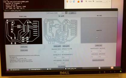 traces
with a voltage meter, I was ready to program! Setting up our USB to serial
converter, a CP2102 breakout board, was simple thanks to this website.
Then began the program writing. I’ve only ever used Arduino to blink an LED
with an UNO once before. I had practiced with a simple light sensor and reading
the data on a breadboard too. I figured I could combine the blink & AnalogReadSerial example code to create mine. It was
difficult and fortunately I had some help from more experienced Arduino users.
My code
was finally programmed onto the microcontroller!
traces
with a voltage meter, I was ready to program! Setting up our USB to serial
converter, a CP2102 breakout board, was simple thanks to this website.
Then began the program writing. I’ve only ever used Arduino to blink an LED
with an UNO once before. I had practiced with a simple light sensor and reading
the data on a breadboard too. I figured I could combine the blink & AnalogReadSerial example code to create mine. It was
difficult and fortunately I had some help from more experienced Arduino users.
My code
was finally programmed onto the microcontroller!